
Welcome to the third article in the series on building my AArch64 bare-metal kernel!
In this article, I’ll present v0.2 of the project. The goal of this version is to implement kernel exceptions: get a kernel able to detect and handle a synchronous exception (via svc) as well as an asynchronous hardware interrupt (IRQ), through a vector table, a synchronous handler, an IRQ handler, and the GIC (interrupt controller).
Here are the files covered in this article, and the section explaining each one:
| File | Role | Section |
|---|---|---|
src/exceptions/vectors.s | Exception vector table | Implementing the vector table |
src/exceptions/handlers.s | Synchronous and IRQ handlers | The synchronous handler and The IRQ handler |
src/gic/gic.s, src/gic/gic.inc | GIC driver (gic_init) | The GIC and the IRQ handler |
src/uart/uart.s | Added uart_put_hex | uart_put_hex |
src/boot/boot.s | VBAR_EL1 configuration, gic_init, triggering svc/SGI | Triggering the synchronous exception and The GIC and the IRQ handler |
The project can be found in this repository: aarch64-baremetal-kernel.
AArch64 exception model#
This section is heavily based on ARM’s official documentation: Learn the architecture - AArch64 Exception Model.
Synchronous and asynchronous exceptions#
In AArch64, there are two types of exceptions:
- synchronous exceptions, caused by (or tied to) the instruction currently executing
- asynchronous exceptions, caused by something external to the instruction flow.
A synchronous exception is directly triggered by the currently executing instruction: a system call (svc), an invalid instruction, or a memory fault, for example. The return address has an architecturally defined relationship with the faulting instruction, and this type of exception cannot be masked — in other words, it interrupts the instruction flow.
An asynchronous exception comes from an external event, for example: a timer, a peripheral, or another core. This is referred to as an interrupt (IRQ, FIQ, or SError). Unlike synchronous exceptions, interrupts can be masked via the PSTATE.DAIF register, and are handled through the GIC (Generic Interrupt Controller), covered later in this article.
In this article, we’ll trigger and handle one example of each type: an svc for the synchronous part, and an SGI (Software-Generated Interrupt) via the GIC for the asynchronous part.
Here are the registers used to handle exceptions:
| Register | Role |
|---|---|
ELR_ELx | Return address after the exception |
ESR_ELx | Cause of the exception (synchronous/SError only) |
SPSR_ELx | PSTATE saved at the time of the exception |
VBAR_ELx | Base address of the vector table |
The
xsuffix depends on the current EL. Since this kernel only runs atEL1, we’ll only useELR_EL1,ESR_EL1,SPSR_EL1, andVBAR_EL1.
eret atomically restores PSTATE from SPSR_ELx and makes the CPU jump to the address held in ELR_ELx. For an svc, ELR_EL1 holds the address of the instruction following the svc.
The vector table#
Each EL has its own vector table, whose address is given by VBAR_ELx. This table holds 16 entries of 128 bytes (32 instructions) each, and must be aligned on 2 KB.
| Offset | Type | Source |
|---|---|---|
+0x000 | Synchronous | current EL, SP_EL0 |
+0x080 | IRQ | current EL, SP_EL0 |
+0x180 | SError | current EL, SP_EL0 |
+0x200 | Synchronous | current EL, SP_ELx |
+0x280 | IRQ | current EL, SP_ELx |
+0x380 | SError | current EL, SP_ELx |
+0x400 to +0x780 | (lower EL, AArch64/AArch32) | unused |
This kernel only runs at EL1, with no EL0. So only the two bolded entries (+0x200, +0x280) matter to us; the rest will be stubs.
Implementing the vector table#
To implement the vector table, I took inspiration from the file 11_exceptions_part1_groundwork/src/_arch/aarch64/exception.s in the rust-raspberrypi-OS-tutorials repository.
The CALL_HANDLER and UNUSED_VECTOR macros#
In a new file, src/exceptions/vectors.s, we’ll build a few pieces:
- First, a macro that calls the correct
handlerfor the requested exception:
.macro CALL_HANDLER handler
vector_\handler:
    mrs x19,  ELR_EL1
    mrs x20,  SPSR_EL1
    mrs x21,  ESR_EL1

    mov x0, sp

    bl \handler
.endm
This CALL_HANDLER macro saves ELR/SPSR/ESR into callee-saved registers (x19-x21) before calling the actual handler, with sp passed in x0.
- Next, a macro that acts as the
handlerfor every other, unimplemented exception:
.macro UNUSED_VECTOR
1:
    wfe
    b   1b
.endm
UNUSED_VECTOR uses a numeric local label so it can be expanded several times in the same file without symbol collisions.
Alignment and .org#
Next, we build the actual vector table:
.align 11

_exception_vector_table:
.org 0x000
    UNUSED_VECTOR
.org 0x080
    UNUSED_VECTOR
...

.org 0x200
    CALL_HANDLER el_synchronous
.org 0x280
    CALL_HANDLER el_irq
...

.org 0x800
First, the table is aligned on 2048 bytes (2 KiB), as required by VBAR_EL1.
Then, .org places each entry at its exact expected offset in the table, advancing the assembler’s location counter as needed.
Most entries in this table point to UNUSED_VECTOR. The two entries we actually care about are at offsets 0x200 and 0x280, where CALL_HANDLER el_synchronous and CALL_HANDLER el_irq are placed respectively.
Triggering the synchronous exception#
uart_put_hex#
Before adding the synchronous exception, we need to add a function to src/uart/uart.s that prints (via UART) a 64-bit value as hexadecimal:
uart_put_hex:
    stp x19, x20, [sp, #-32]!
    stp x30, xzr, [sp, #16]

    mov x19, x0
    mov x20, #16

hex_loop:
    lsr x3, x19, #60
    and x3, x3, #0xF

    ldr x2, =hex_chars
    ldrb w0, [x2, x3]
    bl uart_putc

    lsl x19, x19, #4

    subs x20, x20, #1
    b.ne hex_loop

    ldp x30, xzr, [sp, #16]
    ldp x19, x20, [sp], #32
    ret

hex_chars:
    .asciz "0123456789ABCDEF"
This function is needed because uart_puts only handles ASCII, and the idea here is to print register values on every exception.
The synchronous handler#
In src/exceptions/handlers.s, we define el_synchronous, the function called by CALL_HANDLER. For now, the handler only needs to print information. It starts by printing Synchronous exception caught!\n when called, then prints the values of ELR_EL1, SPSR_EL1, and ESR_EL1.
el_synchronous:
    stp x29, x30, [sp, #-16]!

    ldr x0, =message_synchronous
    bl uart_puts

    ldr x0, =message_prefix_elr_el1
    bl uart_puts
    mov x0, x19
    bl uart_put_hex

    ldr x0, =message_prefix_spsr_el1
    bl uart_puts
    mov x0, x20
    bl uart_put_hex

    ldr x0, =message_prefix_esr_el1
    bl uart_puts
    mov x0, x21
    bl uart_put_hex

    ldp x29, x30, [sp], #16
eretx19, x20, and x21, filled in by CALL_HANDLER, survive the uart_puts/uart_put_hex calls since these are callee-saved registers. The final eret resumes execution right after the instruction that triggered the exception.
All that’s left is configuring VBAR_EL1 and triggering the exception. In src/boot/boot.s:
ldr x0, =_exception_vector_table
msr vbar_el1, x0

...

svc #0
VBAR_EL1 must be configured before any instruction that could raise an exception. The svc #0 then deliberately triggers a synchronous exception, which gets caught at offset +0x200 of the vector table.
Result#
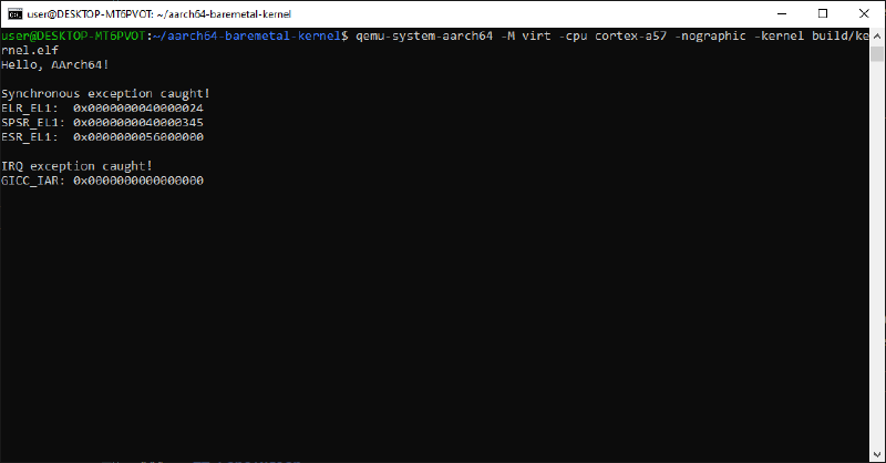
qemu-system-aarch64 -M virt -cpu cortex-a57 -nographic -kernel build/kernel.elfHello, AArch64!
Synchronous exception caught!
ELR_EL1: 0x0000000040000024
SPSR_EL1: 0x0000000040000345
ESR_EL1: 0x0000000056000000ESR_EL1, bits [31:26] (theECfield) =0x15, the exception class forSVCin AArch64.
SPSR_EL1, bits [3:0] =0x5=EL1h(EL1,SP_ELx).
ELR_EL1(0x40000024) does indeed match the address of the instruction followingsvc #0(0x40000020) inboot.s, verifiable viaaarch64-none-elf-objdump -d build/kernel.elf:
0000000040000000 <_start>:
    ...
    4000001c:   d50342ff        msr     daifclr, #0x2
    40000020:   d4000001        svc     #0x0
    40000024:   58000160        ldr     x0, 40000050 <_start+0x50>
    ...
The GIC and the IRQ handler#
Once again, for this part I relied on ARM’s official documentation: Arm Generic Interrupt Controller Architecture Specification (GICv2). QEMU virt with cortex-a57 implements a GICv2.
Distributor and CPU interface#
The GIC (Generic Interrupt Controller) is ARM’s standard interrupt controller: a centralized resource sitting between every interrupt source and the CPU.
The GIC is split into two blocks:
| Block | Role | Prefix |
|---|---|---|
| Distributor | Centralizes sources, prioritizes | GICD_* |
| CPU interface | Per-processor priority masking | GICC_* |
An interrupt’s lifecycle follows three steps:
- Acknowledge: reading
GICC_IAR, which returns the ID of the pending interrupt and moves it to the active state. - Handle: the handler runs.
- Complete: writing the same value back to
GICC_EOIR.
Finding GICD_BASE / GICC_BASE#
As with the UART, we need to find the base address of these two components (the distributor and the interface):
qemu-system-aarch64 -M virt -cpu cortex-a57 -machine dumpdtb=virt.dtb -nographic
dtc -I dtb -O dts virt.dtb | grep -A 5 intc
We get:
        intc@8000000 {
                phandle = <0x8002>;
                reg = <0x00 0x8000000 0x00 0x10000 0x00 0x8010000 0x00 0x10000>;
                compatible = "arm,cortex-a15-gic";
                ranges;
                #size-cells = <0x02>;
Per the standard arm,gic device tree binding, the Distributor is listed first in reg:
| Register | Address |
|---|---|
GICD_BASE | 0x08000000 |
GICC_BASE | 0x08010000 |
These addresses are confirmed directly in QEMU’s source code: hw/arm/virt.c defines
VIRT_GIC_DISTas0x08000000andVIRT_GIC_CPUas0x08010000.
gic_init#
The register offsets used are grouped in a separate file, src/gic/gic.inc, so they can be shared across several .s files:
.equ GICD_BASE,       0x08000000
.equ GICC_BASE,       0x08010000
.equ GICD_CTLR,       0x000
.equ GICD_ISENABLER0, 0x100
.equ GICD_SGIR,       0xF00
.equ GICC_CTLR,       0x000
.equ GICC_PMR,        0x004
.equ GICC_IAR,        0x00C
.equ GICC_EOIR,       0x010
In src/gic/gic.s:
gic_init:
    ldr x0, =GICD_BASE
    mov w1, #0x1
    str w1, [x0, #GICD_CTLR]      // enable Group 0 forwarding

    ldr x0, =GICD_BASE
    mov w2, #0x1
    str w2, [x0, #GICD_ISENABLER0] // enable SGI 0

    ldr x0, =GICC_BASE
    mov w3, #0xFF
    str w3, [x0, #GICC_PMR]        // let all priorities through

    ldr x0, =GICC_BASE
    mov w4, #0x1
    str w4, [x0, #GICC_CTLR]       // enable Group 0 signaling

    ret
.include pastes the content of gic.inc directly into the file at assembly time. This is needed because an offset used as an immediate ([x0, #GICD_CTLR]) must be known to the assembler at assembly time, not just at link time. The Makefile passes -Isrc so .include "gic/gic.inc" resolves relative to src/.
gic_init therefore configures four things:
- enabling
Group 0interrupt forwarding at the Distributor - enabling
SGI 0 - the CPU interface’s priority mask (
0xFF= let everything through) - and enabling
Group 0signaling on the CPU interface side.
This function is called once, early in _start, in src/boot/boot.s:
bl gic_initThe IRQ handler and triggering the SGI#
The IRQ handler does roughly the same thing as the synchronous handler (print a message and a register in hexadecimal, then eret). However, there’s only one register to print (GICC_IAR), and it needs to go through the GIC’s Acknowledge/Complete cycle seen above:
el_irq:
    stp x22, x30, [sp, #-16]!

    ldr x0, =GICC_BASE
    ldr w22, [x0, #GICC_IAR]       // moves the interrupt to active

    ldr x0, =message_irq
    bl uart_puts
    ldr x0, =message_prefix_iar
    bl uart_puts
    mov x0, x22
    bl uart_put_hex

    ldr x0, =GICC_BASE
    str w22, [x0, #GICC_EOIR]      // write back the exact value read

    ldp x22, x30, [sp], #16
    eret
x22 is used instead of x19-x21 (already reserved by CALL_HANDLER for ELR_EL1/SPSR_EL1/ESR_EL1) so the value of GICC_IAR survives the calls to uart_puts/uart_put_hex.
We start by unmasking IRQs, masked by default at reset. Still in src/boot/boot.s:
msr daifclr, #2Then, in src/boot/boot.s, write to GICD_SGIR to trigger the SGI:
ldr x0, =GICD_BASE
mov w1, #0x2000000
str w1, [x0, #GICD_SGIR]
0x2000000 encodes TargetListFilter = 0b10 (bits [25:24], targets the current processor only) combined with SGI ID 0 (bits [3:0]). This write immediately triggers the interrupt, which is caught at offset +0x280 of the vector table.
See the GICv2 Architecture Specification for the
GICD_SGIRencoding (TargetListFilterin bits [25:24], SGI ID in bits [3:0]).
Build and verify#
We start by building and checking that the expected symbols are present:
make clean && make
aarch64-none-elf-nm build/kernel.elf | grep -E "exception_vector_table|el_irq|el_synchronous|gic_init"
0000000040000800 T _exception_vector_table
00000000400000a4 T el_irq
0000000040000058 T el_synchronous
0000000040001000 T gic_init
0000000040000a80 t vector_el_irq
0000000040000a00 t vector_el_synchronous_exception_vector_table sits at address 0x40000800, a multiple of 0x800 (2048), confirming the linker honored the 2 KB alignment required by VBAR_EL1.
We also find
vector_el_synchronousandvector_el_irq, the local labels generated respectively byCALL_HANDLER el_synchronousandCALL_HANDLER el_irq, at0x40000800 + 0x200 = 0x40000a00and0x40000800 + 0x280 = 0x40000a80. Both entries are correctly routed to their expected offsets in the table, so everything checks out.
Finally, we launch the kernel with QEMU:
Conclusion#
The kernel now has its own vector table (still to be fully populated) along with basic handlers for the implemented vectors.
Thanks for reading all the way through, and see you in the next article: Setting up the ARM timer.